This is a blog for my 3d printer built and arduino examples.
I am a lecturer in Robotics and I like to share some of what I had done and what my students had done.
Also I will share how to design a good 3D printable object.
Many people design 3D parts for art, beauty or decoration. I found that plastic injection molding do a better job. My primary 3D printing is for engineering purpose. So I am more concern about the dimension accuracy and strength of objects. I like to use PLA and ABS if I really need to.
Did you ever had the frustration where by you took something from thingiverse and JUST PRINT IT.
Oh my god, it print nicely but it does not fit.
First, you need to know your printer print out accuracy. It applied to external dimension ( overall length, width and height) and internal like holes, slot, fillet etc.
If you design a hinge , you need to know how much offset it will really print. Let take this as an example. If your thickness of the yellow colour hinge is wrong, you can never fit in. Lets say the space between 2 blue hinge is 4 mm. so you thickness cannot be 4mm. if you know you print out will be about 4.1mm, then you can safely set you width to be 3.7 to 3.5. Always reduce your thickness by about 0.2 mm or more.
Next the hole. You might ask HOW BIG SHOULD THE HOLE SIZE BE ?
This guidelines is exactly the same as normal drilling. If you screw is 3mm, you hole should be 3.5 mm. Unless you can get a very accurate printout, but remember, beside the hole size, your position will be offset. I do not like to do too much post procession like drilling to enlarge the hole, because you will cause the hole structure to weaken. I find that some Thingiverse user draw hole which is EXACTLY the same size as screw....
Next adding fillet to the parts. what is a fillet. fillet has 2 used. one is for strength, one is for smoothness.
to be continued ....
Let me share with everyone how to get a good print out.
First since 3D printer is a precision equipment, if your components are not precise, you will never get a good printout for a reasonable time. eg, use of threaded rod may not be ideal for a long time.
Let's assume, you have a structurally stable and good print head or extruder.
First in order to print well, look at the first layer. If it print well, you will more likely to get a good printout. If it does not, the structure will move and you will a pile of rubbish.. what do I mean by a good first layer. Assume that you had calibrated the flow rate and you do not get something like this....
1) Print bed slanted - You will see one side is crushed and the other side does not stick well.
Remedy : make the bed flat or it could be your print head is slanted.
2) Print head too high - the print out just does not stick to surface .
Remedy : I prefer to adjust the Z offset in my slicer program. it is easier because your are talking about probably 0.1 to 0.4 mm. Adjust your stop switch will be tough.
3) print head too low - will cause excessive adhesion to surface. Filament will get compressed on the surface and if you see carefully, you will see that it is very flat and enjoy your hard time getting the pieces out of the heated bed. I prefer to adjust this by the Z-offset also. It is easier.
This print out is good. A little more will crush and compressed the print out.
Next let's talk about the various type of surface to print on.
1) kapton tape: My experience is, it is not very sticky and in the surface is too little , the printout will dropout. So I will definitely put a raft layer as a interface layer. I use it on the Felix printer.
2) Uhu Glue on glass - The prusa I have is using UHu glue on glass. It sticks really well. even when the base is small. Usually I apply 1 time, I can use it for many print.
3) Blue painter tape: the adhesion is pretty strong also, but sometime, it just come out with the printout. So I find it quite a trouble to reapply the blue tape.
I will edit with more pictures when I gather them ...
I am very fortunate that I used many of the 3D printers due to my work. Lets just talk about reasonable one. And forget about those that cannot make it.
Felix - The program, print is very good at the price of the printer. But I find that it does not stick to surface of the heated bed well. often need to add additional perimeters to stablelize it. Sometimes, half way through, the object just lift up and drop ...dead... Other than that it is fine, especially when I print honey comb structure.
Next , I used Uprint. This is a more professional machine than the conventional Reprap family. It used propietry filament and support material. They sell in a carton of 7 sets. Costing about USD 1 K per box. The filament is ABS. The support material is soluble in acid. Print out is very hard, professional. But cost wise, it is higher. The support material is actually not so hard to take out, even if you are using simple tools like penknife and screw driver. Unless REPRAP machine, the support material is the same and hence hard to take out. Even if u can, it take a long time to clean up.
Also with this machine, I can tilt or adjust my printing to suit the force exerted on the layers. As we know, one of the weakness of 3D printing is due to the layers. If you exert a force parallel the layers, it might give way. So for Uprint, we can tilt the angles of the print out till the forces are not parallel to layering. Of course at the expense of the support material.
Next, we have OBjet.
OBjet is very expensive.The material is also very expensive. I would have though that this machine can print out molding quality. But I discover I was wrong. Conventional 3D printer including Uprint uses material that is quite brittle and not soft like injection molded plastic. So under pressure, the printout might crack or give up. With OBjet, I thought it will be much better. Later I realised that this is not the case. It still crack. Although the material is better the PLA or ABS.
The printout is super smooth. It actually flatten every layers and make a smooth surface.
Another problem with OBjet is, you need to go through washing to clean the parts, as the parts is still wet after printing. Cleaning will take a you while to do it. You can see it is very well protected, the material could be a bit toxic. The material is VERY expensive.
I had bought quite a few hotends. I bought
1) J-head , Aluminium nozzle , Plastic body
2) J-head with aluminium heat sink and brass nozzle.
3) Mk7Direct extruder
4) E3D Hotends.
Also , I had many sizes of nozzles. 0.2 to 0.5 And in the end, I prefer to use 0.4.
Let's talk about this type of J head hot end. Plastic high temperature body and aluminium nozzle. The nozzle is relatively expensive to replace. I use it when I first started my Prusa I3. What happen is even with this body, YOU NEED A COOLING FAN. If not, your PLA might melt and solidify in it.
This nozzle clot easily. residue stick to Aluminium and hence you will find that the flow gets smaller and smaller. Then after I cleared it, one might accidentally enlarge it. Because Aluminium is soft. How I clear the choke. Basically I heat it using bare flame of my cooking hob. Then I have to get a stiff wire or the right size drill bit to clear it. After clearing afew times, I got fedup with it. I changed to brass nozzle. And stop using J head. Now I have 2 sets of J head with 3 nozzles.
Next I bought a all metal J-head. I bought it cheap. probably less than 5 USD. I bought the heat sink , stem and nozzle separately. It works very well. Only thing is , YOU MUST HAVE A COOLING FAN. If you do not put a fan, the PLA filament will melt in the heat sink portion and solidify. then it will be hard to extrude. I machined My own heater block. Just for fun. Now I am still using this extruder/ hotend. The Brass nozzle is very important . It just don't choke. Ever since using this, I had never need to resort to barbeque my nozzle. I used a 0.4 mm nozzle.
Also I tried using direct extruder. Mk7 direct extruder with non contact heat sink but with fan.
This is a very simple but good extruder. Once I realised that maybe I do not need geared extruder, I put this into use. with indirect heat sink and fan. It works quite well but I still prefer the all metal j-head. I do get jam once in a while. But I think probably I did not set it well. I think this is simple and good. and importantly, nozzle must be brass.
lastly, I bought a E3D hotend. this is just a smaller version of all metal J-Head. so the result is comparable, but the size is smaller.
Additional cooling fan for the printed parts. I had a chance to use Felix 3D printer. I am very impressed by the printout. It is so simply built and printout is so good. I realised from Felix that you need another cooling fan for the printout. This is to make sure that the previous layer harden and make the structure more rigid. especially at slope. previous layer need to solidify or else some times, you see a big lump on the curve or slope at the side of it.
avrdude: stk500_getsync(): not in sync: resp=0x0 A lot had been written about the error, but mine was solved loading bootloader.
I believe flashing boot loader is nothing new. But the process may be abit tricky.
I used Arduino uno to program the Mini driver boot loader. Yes, you may be right. You need another arduino to program the one which you need a new bootloader. Common one is UNO. How to do it ?
1) connect you arduino Uno to PC using USB cable.
2) Select the correct port to connect. If you do not know, go to Control panel - > device manager -> ports to look for the port arduino Uno is connected. If you cannot find, that means Uno is not recognized in your system.
3) select the correct board to connect. In my case Arduino Uno ( not yet mini driver.)
4) In the arduino programmer, load the program called ArduinoISP. Upload it into arduino Uno.
5) Next connect your Uno to Dagu Mini driver.
6) Now in the arduino programmer, change the board to Arduino NG or older with ATmega 8.
You probably need to set programmer as USBasp.
7) Now goto Tools -> burnt boot loader.
8 ) Now you are done. You can now directly detect and upload the mini driver.
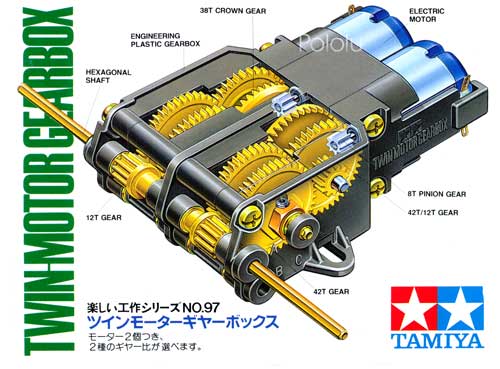
To set up a Bluetooth vehicle using Dagu mini driver and Bluetooth is so easy. Take a look at my configuration. You can use Tamiya base plate or cut your own aluminium base plate, or 3D print it. Also I am using a Tamiya twin gearbox motor to driver the car. You must be wondering why need gear box ? can't we just driver directly from the motor ? The answer is NO ! DC motor is running at a very high speed. so you car could be running too fast. and it consume too much current.
Another setup using 3D printed base and arduino Nano.
Next, Mount the motor onto the base plate . Connect Lipo / AA/ NiCD/NIMH batteries to it. I am using some 4X AA batteries holder for this. I also used ball castor for free rotation. It is a bit noise and ruse easily .
For those who bought the Dagu robot, these are the alternative program to start with .
You can find more information at Dawn robotics blog .
Demo program for a car controlled by Dagu mini driver.
You can actually turn this program into a line tracker using IR sensor like TCRT5000,
or using sonar sensor to detect walls.
Hope this make a good start. If you need, change the motor speed as needed.
// Demo program for the Dagu Arduino Mini Driver. Uses dead reckoning
// Try changing the maximum value to 100 if your car is running too fast.
digitalWrite( LEFT_MOTOR_DIR_PIN, HIGH );
digitalWrite( RIGHT_MOTOR_DIR_PIN, HIGH );
analogWrite( LEFT_MOTOR_PWM_PIN, 255 );
analogWrite( RIGHT_MOTOR_PWM_PIN, 255 );
delay( DRIVE_FORWARD_TIME_MS );
// Turn right at 50%. Stop right motor on left motor.
// you can change the value from 128 to lower.
digitalWrite( LEFT_MOTOR_DIR_PIN, HIGH );
digitalWrite( RIGHT_MOTOR_DIR_PIN, LOW );
analogWrite( LEFT_MOTOR_PWM_PIN, 128 );
analogWrite( RIGHT_MOTOR_PWM_PIN, 128 );
delay( TURN_TIME_MS ); With these, you can easily start you Dagu vehicle. You can check out Dawn robotics for their program with Bluetooth, which could be harder for some to understand.
I bought a Dagu mini driver with bluetooth . I wanted to set up a easy remote control robot using any android phone. This arduino based driver fit what I wanted . I had 2 motor driver, 8 digital ports and 6 analog ports. And also 1 port ( of 4 pins ) for bluetooth module. This module is very useful for my purpose. 2 ports for motor, 8 ports which can be used for servo. 6 ports for any analog sensor.
There is also a switch on it. Built in diode to prevent plunging power supply in the wrong way.
Perfect !!!
I got into some problem initially . Arduino error :
avrdude: stk500_getsync(): not in sync: resp=0x0
I tried many ways to solve it, search through the web and discover nothing (to my surprise ).
So in the end I solved it by flashing the boot loader . How to flash the boot loader ? I shall do it another day.
First, for all Arduino, Bluetooth module must be remove before uploading.If in the event that you had damaged the bootloader, you can flash it. Remember take out the bluetooth first.
Next configure the bluetooth. Go to Play Store to find the app name Bluetooth Serial Controller .
Install it . Run it . Activate the Connect tab, and it shows you Bluetooth device that you can connect.
Choose HC-06 to connect. If this is the first time you connect, the password is 1234.
When it is connected the Bluetooth light will not flash anymore. Then , it is connected. Next configure your buttons. I has configure it to all these. You can hide, change functions, change text etc.I am preparing for a soccer playing Bluetooth remote control robot. So I have forward and reverse. left and right. Strike, defend and block. let us see how we do it.
At the PREFERENCE tab, once you click it, you can see
options like Name, command visibility etc
Name , as it implies will show the name . Click on it, change the name of the buttons to what you want. You can see that I changed the buttons name for buttons 2,5,6,7,10, 4,8,12.
Next change the command for the buttons.
"0" = forward
"1" = backwards
"2 " = left
"3" = right.
"4" =stop.
You can add some more commands to buttons but you have to change the Arduino programs.
Next we change the visibility to invisible. We are only interested in some layout and we want to hide some buttons. Or else we will mispress the buttons. The options is a tick box.
Next the arduino program that I used
// Modified by jack on Jan 2015
// Program for dagu mini controller.
//Standard PWM DC control
int M2 = 7; //ML Direction Control
int M1 = 8; //MR Direction Control
int E2 = 9; //ML Speed Control
int E1 = 10; //MR Speed Control
void stop(void) //Stop
{
digitalWrite(E1,LOW);
digitalWrite(E2,LOW);
}
void advance(char a,char b) //Move forward
{
analogWrite (E1,a); //PWM Speed Control
digitalWrite(M1,HIGH);
analogWrite (E2,b);
digitalWrite(M2,HIGH);
}
void back_off (char a,char b) //Move backward
{
analogWrite (E1,a);
digitalWrite(M1,LOW);
analogWrite (E2,b);
digitalWrite(M2,LOW);
}
void turn_L (char a,char b) //Turn Left
{
analogWrite (E1,a);
digitalWrite(M1,LOW);
analogWrite (E2,b);
digitalWrite(M2,HIGH);
}
void turn_R (char a,char b) //Turn Right
{
analogWrite (E1,a);
digitalWrite(M1,HIGH);
analogWrite (E2,b);
digitalWrite(M2,LOW);
}
void setup(void)
{
int i;
for(i=7;i<=10;i++)
pinMode(i, OUTPUT);
Serial.begin(9600);
Serial.println("-----LED Bluetooth Control-----");
From the Prusa I3 orginal documentation, I downloaded the STL file and assembled the extruder. Assembled as they taught and mounted it on. The only problem is I used J head. I was not sure whether J head can be mounted onto it.
Let's talk about the gear head. It works well. For so long, the gear did not fail at all. still hard and steady. And I use PLA to print it.
To confess, the PLA printout from Cube 3D sucks. I am not sure how long it will last. but I know, as long as I get it to work, I will duplicate all the printed parts again....
After completed building it, it is time for my first few prints....
There are afew basic print to determine whether your printer is doing a fine job. A hollow box like this....This shows that the printer did follow the path, but the hot end did not do a good job.....
After that I tried to print a solid box 20mm X 20mm. It look like a sponge. This shows that I did not calibrate properly. A better one look like this,....
You can see the cross line being clearly laid out.....The print was much better...
You can see that the line are pretty much aligned... also... that is good. But not the end.
Building that was easy.... Simply cut the M10 threaded rod , re-thread the rod ends. Bolt and nut it.
Had alot of cable tie on hand. It is needed to tie many things...
That is all. But I found a problem. I do not know what size( height of the NEMA 17) the motor used in the drawing given, so after I built it , the Nema 17 DID NOT TOUCH THE FLOOR......
So I added a piece of supported printed from the 3D printer , after I fully make it work... but the print was bad... You can see the wave print . But not bad consider that I had not fully optimize it....
The Heated Bed support and the vertical plate is machined from 1 piece of 8mm acrylic that I salvage from somewhere. So it is considered free . If you do not have a milling machine, you can consider buying it. For your info, you need not machine it until like this. I simply had a rectangular plate. It is not that heavy. I was lazy and the milling machine was not that good, So I did not reduce the size too much... But I managed to cut some slots for the linear bearings...
For Heated Bed I used Mk2. Now Mk3 is produced. It will be good as you can possibly lift the bed rather than lowering the extruder. MK2 must be mounted with a flat surface glass. I salvaged a a scanner glass and cut to size...
Mk 2B.
The New Mk3 is availlable and it has a aluminium layer on it. So not more glass panel. This is good. I will use Mk3 when I have a chance. But becareful when you buy MK3, Make sure it is MK3. Some supplier make MK2a/2b BLACK.......
Easy to built ... It is a big yes !
Robust .............No, can do better,
Let me talk about the MECHANICAL BUILT !!!?
If you look at the side view of the printer, you will know it is not stable. The vertical plate is only locked with M10 nut. It will FLEX .... The Extruder is providing a big moment on the structure, so it will have a clock wise moment . If your structure is not stable, the print out will be messy.
So some people added more structure to stablelize it. Like this.
Additional Rib to stablize the structure during printing. In my case, I added 2 plates which I salvaged from somewhere to stabilize it. Its free...
Stability is very important . If you want better stability. Like this ... You can consider using Aluminium Profile 20X20mm Or 30X30mm. I seen Felix 3D printer used 40X40 mm profile. Like the Reprap wilson , 3Drag or even Felix .
Why is Prusa with Acrylic body or Aluminium plate not an ideal structure ?
What is a good structure for 3D printer ?
First, the body should not flex in any condition. Prusa Flex.... Mendel could be a better choice.
Second, the extruder exert a force and moment on the body. If it causes flexing it is not good.
Prusa has 2 supporting shaft vertically inline. It is not as good as Mendel where 2 shaft are horizontal. Of course it is easy to solve by making sure that you have additional support at the center of gravity.